[Top] [Table Of Contents] [Prev] [Next] [Index]
4 out of 16 total pages
 

PortMaster 4 Overview   1


  This chapter provides the following overview of PortMaster 4 basic operation and components:
 

       How the PortMaster 4 Works

  The PortMaster 4 consists of one or more line boards and an Ethernet board, all managed by a system manager board. The Ethernet board and manager board together make up the system manager module . You configure and manage the lines and Ethernet interfaces via the PortMaster ComOS operating system. Security is provided by RADIUS or PortAuthorityTM RADIUS software.
  The following sections describe how the components of the PortMaster 4 interact.
 

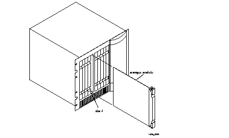
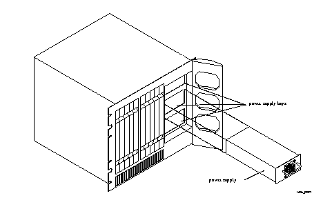
       Slots, Boards, and Power Supplies

  The front panel of the PortMaster 4 includes the following:
 

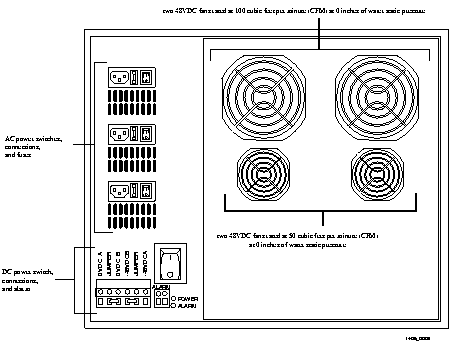
       Fans, Switches, Fuses, and Connectors

  The rear panel of the PortMaster 4 includes the fans, switches, connections, and fuses shown in Figure 1-3.

  Figure 1-3 Rear Panel


       ComOS Software

  Every PortMaster product comes with Lucent ComOS operating system software installed in nonvolatile RAM. This software is periodically updated. New releases are announced on the PortMaster mailing lists and are available by anonymous FTP from ftp://ftp.livingston.com.  See "About This Guide" for information on mailing lists.
  Each board in the PortMaster 4 has a ComOS that is specific to its operation.
  Use one or both of the following interfaces to ComOS to configure operational settings, collect statistics, upgrade software, busy-out modems and circuits, and monitor calls in progress from a central site:
  The instructions in this guide cover only the command line interface. Access PMVision online help for more information about using PMVision.
  You can manage the PortMaster 4 from a PC or terminal directly connected to one of the chassis' two console ports, or via an SNMP, Telnet, or dial-up connection to one of these ports.
 

       System Manager Module

  The system manager module is made up of the manager board and an Ethernet board. The manager module is responsible for
  The system manager board communicates with installed boards at 155Mbps using an embedded Asynchronous Transfer Mode (ATM) cell backplane. The Ethernet board attached to each manager module provides one 10/100Mbps Ethernet port and an alternative media-independent interface (MII) connection. The Ethernet board also manages the 10Mbps Ethernet management port that is physically located on the manager board. The manager board uses a 486DX5 processor, and the Ethernet board uses dual R4640 processors.
  The configuration settings for all installed line boards are stored in the nonvolatile RAM of the system manager board. Because these settings are associated with the slot in which the board resides rather than the board itself, you can remove a failed board and insert a new board in the same slot without having to reconfigure it. When the replacement board is turned on, it retrieves its configuration from the system manager board.
  The system manager module is currently not hot-swappable, and its disconnection stops the PortMaster 4 from working. However, you can replace a failed manager module without shutting down power to the PortMaster 4.
 

       Views

  The PortMaster 4 is a group of different boards in one chassis that you administer both together and separately. To monitor and configure a particular board, you set the view to the slot number where the board resides with the set view  command. The default view is slot 4, which is the system manager view.
  The command line prompt indicates the view you are in, except in the case of the system manager board for which the prompt displays no view number.
  The save all  command saves all configurations on all boards, regardless of what view is set.
 

       Power Management

  The PortMaster 4 chassis is powered by up to three AC power units and/or a -48VDC backplane. The backplane sources -48VDC through a dual-input rear-panel connector. Each removable AC power unit supplies 400W to the PortMaster.
  Each installed board requires about 80W of power. A fully loaded PortMaster 4 requires a power budget of 800W, requiring two AC power supplies or a DC power connection. You can install an optional third AC power supply as a backup.
  Before turning on an installed board, the PortMaster 4 determines how much power it requires. If enough power is available in the power budget, the PortMaster 4 supplies power to that board. If not enough power is available in the power budget--if, for example, one of the power units has failed--the PortMaster 4 leaves the board turned off and generates an SNMP alarm.
  If, in the course of operation, the PortMaster 4 has a drop in its power budget and cannot run all its installed boards, it turns off boards until the power budget is balanced. Boards are turned off first by type and then in order of slot number, beginning with the highest-numbered slot. Line boards are turned off first. The manager board and Ethernet board are never turned off due to a shortage of power.
  You can view information about power usage of installed boards by using the show slots  command from the system manager board view.
 

       Temperature Management

  The PortMaster 4 is air-cooled by four fans. The air in the chassis is pulled from front to back, and from bottom to top. The system manager board constantly samples the internal temperature of the chassis and issues an SNMP alarm if the temperature rises above 50oC (122oF). If the temperature rises above 55oC, the system manager board begins turning boards off until the temperature goes below 50oC (113oF). Boards are turned off in order of slot number, with the highest-numbered slot being turned off first.
  You can specify a different shutdown temperature between 30oC and 90oC (86oF and 194oF) by using the set shutdown temp  command. For more information about this command, see the PortMaster 4 Command Line Reference.
  If a fan fails, an SNMP alarm is generated. Fan loss does not directly cause a board to be turned off.
 

       Line Boards

  See the individual board chapters later in this guide for descriptions of the line boards currently available on the PortMaster 4.
 

       Security Management

  RADIUS Software.  The Remote Authentication Dial-In User Service (RADIUS) client/server security protocol created by Lucent is shipped with the PortMaster 4. RADIUS provides a central storage and delivery mechanism for user authentication, authorization, and accounting. User information updates can be made and stored in one place, rather than throughout the network. See the RADIUS for Windows NT Administrator's Guide or the RADIUS for UNIX Administrator's Guide for details.
  PortAuthority TM RADIUS Software.  Lucent's PortAuthority RADIUS provides enhanced RADIUS functionality and must be purchased separately.
  ChoiceNet Software.  Lucent's centralized packet-filtering application can be used with either RADIUS or RADIUS ABM to control user access into and out of your network. ChoiceNet is shipped with the PortMaster 4. See the ChoiceNet Administrator's Guide for details.
 

       Services Supported

  ISDN Primary Rate Interface (PRI) Service.  
  Fractional ISDN Service.  You can configure the PortMaster 4 for fractional ISDN service where it is supported by the telephone company. Fractional ISDN is a partial PRI service consisting of between 1 and 22 B channels.
  Channelized T1 Service.  If ISDN PRI service is unavailable, or too expensive, the PortMaster 4 can connect to channelized T1 circuits for dial-up access supporting twenty-four 56Kbps data channels with robbed bit in-band signaling. When using channelized T1 lines, the PortMaster 4 can accept both modem and ISDN calls.
  Channelized E1 Service.  Similarly, for European users, the PortMaster 4 can connect to channelized E1 circuits for dial-up access supporting 2.048Mbps that is subdivided into thirty 64Kbps B channels with generic or multifrequency R2 (MFR2) signaling.
  Full T1 or E1 Service.  The full digital line capacity, minus framing, can be used for a leased line or Frame Relay connection. T1 provides 1.536Mbps, and E1 provides 1.984Mbps. When configured for a full T1 line or E1 line, ComOS creates a WAN interface that can be configured as a hardwired leased line or Frame Relay connection.
  Fractional T1 or E1 Service.  The PortMaster 4 operates over T1 and E1 lines in fractional data rates selectable in any multiple of 64Kbps (T1 or E1 lines) up to the line capacity. This feature is frequently used for Frame Relay or point-to-point communications.
  Channelized T3 (T3 Multiplex) Service.  The PortMaster 4 can be equipped to accept 28 DS-1 signals multiplexed into a T3-rate line.
 

       Fault-Tolerance Features

  The PortMaster 4 employs the following fault-tolerance features:
 

       SNMP Monitoring

  The PortMaster 4 generates SNMP alarms under the following conditions:
  You can view SNMP alarms by using the show alarms  command. You can clear SNMP alarms by using the clear alarms  command. See the PortMaster 4 Command Line Reference for more information about using these commands.
 

       Functional Specifications

  Figure 1-1 lists the functional specifications for the PortMaster 4.

  Table 1-1 Functional Specifications  

 
  Capabilities    Specifications 
 TCP/IP

  · Internet Protocol (IP)

  · Transmission Control Protocol (TCP)

  · User Datagram Protocol (UDP)

  · Internet Control Message Protocol (ICMP)

  · Address Resolution Protocol (ARP)

  · Internet Packet Exchange (IPX)--ComOS 4.1 only.

 Routing protocols

  · Routing Information Protocol (RIP) and RIP-2

  · Open Shortest Path First (OSPF)

  · Border Gateway Protocol version 4 (BGP-4)

  · Static routes

 LAN connectivity

  · One 10/100Mbps full-duplex Ethernet or media-independent interface (MII)

  · One 10Mbps full-duplex Ethernet interface

 WAN connectivity

  · Synchronous and asynchronous Point-to-Point Protocol (PPP)

  · Dynamic IP address assignment

  · Password Authentication Protocol (PAP) and Challenge Handshake Authentication Protocol (CHAP)

  · Multilink PPP

  · Bandwidth Allocation Protocol (BACP)

  · Stac LZS and Microsoft MS-Stac compression

 ISDN switch types

  · In North America --Lucent 5ESS and 4ESS, Nortel DMS-100, National ISDN-1 (NI-1), and NI-2

  · In Europe --NET3 and NET5

  · In Japan --NTT and KDD

 Signaling

  · T1 robbed bit in-band

  · Foreign exchange station (FXS) loop start

  · Immediate start

  · E&M wink start

  · R2 E1 in-band

 Modem protocols

  · ITU-T V.90

  · K56Flex

  · V.34

  · V.32bis

  · V.22 Bell 212A and 103J

  · V.42 and Microcom Networking Protocol (MNP) 2 through MNP 4 for error control

  · V.42bis and MNP 5 for data compression

 Security and accounting

  · RADIUS authentication, authorization, and accounting

  · Local user password

  · PAP and CHAP

  · Calling line ID

  · Callback

  · Packet filtering

  · ChoiceNet server support

  · Token cards--SecurID and ActivCard

  · Layer 2 Tunneling Protocol (L2TP)

  · IP Encapsulation within IP (IPIP)

 Configuration and management

  · Two asynchronous console ports

  · Telnet

  · PMVision

  · BOOTP

  · Trivial File Transfer Protocol (TFTP) network downloads

  · Simple Network Management Protocol (SNMP) compliance--MIB I, MIB II, and Enterprise MIB extensions

 Chassis capacity

  · In North America --864 modem connections or ISDN B channels, 36 T1 or PRI lines, or one T3 circuit

  · In Europe --810 modem connections or ISDN sessions, or 30 E1 or PRI lines


[Top] [Table Of Contents] [Prev] [Next] [Index]
4 out of 16 total pages
spider@livingston.com
Copyright © 1999, Lucent Technologies. All rights reserved.