[Top] [Table Of Contents] [Prev] [Next] [Index]
5 out of 16 total pages
Installing Core PortMaster 4 Components 2
PortMaster 4 Installation Steps
- Use the following checklist to install core PortMaster 4 components:
o Choose a Site (see page 2-1)
o Prepare the Work Area (see page 2-2)
o Unpack the PortMaster 4 (see page 2-6)
o Attach the PortMaster 4 Chassis to a Rack (see page 2-7)
o Install a Cable Guide (see page 2-8)
o (Optional) Install AC Power Supplies (see page 2-8)
o Install the Manager Module (see page 2-10)
o Connect a Console (see page 2-13)
o (Optional) Connect an External Modem (see page 2-15)
o Connect an Ethernet Cable (see page 2-16)
o Cover Empty Slots with Blank Modules (see page 2-20)
- To install a line board, see the chapter on that board later in this guide.
Choose a Site
- Follow these guidelines to select a site for your PortMaster 4.
Environment
o Choose a clean, dust-free environment.
o Choose an area without direct sunlight, close proximity to heat sources, or high levels of electromagnetic interference (EMI).
Chassis Accessibility
o Provide a 19-inch (49cm) rack for mounting the PortMaster 4.
o Provide 3 inches (8cm) clearance at the front of the PortMaster 4 for cabling purposes.
o Provide 18 inches (46cm) clearance at the front of the PortMaster 4 for module installation.
Air Flow and Cooling
o Provide 3 inches (8cm) around all vent openings of the PortMaster 4 for proper air flow.
o Ensure that the operating environment of the PortMaster 4 does not drop below 41oF (5oC) or exceed 113oF (45oC).
Power Guidelines
o Ensure that the power source of the PortMaster 4 is properly grounded and falls within the internal power supply rating.
¯ PortMaster 4 AC models operate correctly at any AC voltage from 100VAC to 240VAC and frequencies from 47Hz to 63Hz.
¯ PortMaster 4 DC models operate correctly at a DC voltage level of -48VDC.
DC power must be provided through cables with ratings matching the input voltage and current requirements of the PortMaster.
o Ensure the circuit that the PortMaster will connect to can provide the proper voltage. Power draw for the PortMaster 4 is as follows:
¯ A -50VDC fully loaded chassis draws 18 amps.
¯ A 100VAC fully loaded chassis draws 9 amps.
¯ A 200VAC fully loaded chassis draws 4.5 amps.
Prepare the Work Area
- Prepare for installation by gathering this equipment and following these safety recommendations.
Required Equipment
o Number 1 Phillips screwdriver
o 5/32-inch flathead screwdriver
Safety Recommendations
o Keep the chassis area clean and dust-free during and after installation.
o Disconnect the PortMaster 4 from the power source before working near power supplies, changing a fuse, or upgrading memory.
o Before applying power, look for possible hazards such as moist floors, ungrounded power extension cables or missing safety grounds, and locate the emergency power switch for the room in which you are working.
o Wear safety glasses when working under any conditions that might be hazardous to your eyes.
o Keep tools away from walk areas where you and others could fall over them.
o Do not work alone if potentially hazardous conditions exist.
o Wear a grounding strap when handling the internal components of the PortMaster 4. (See "Grounding Wrist Strap Instructions" on page 2-3.)
Warning ¯  (DC models only) Before working on equipment that is connected to power lines, remove jewelry such as rings, necklaces, and watches. Metal objects will heat up when connected to power and ground and can cause serious burns or weld the metal object to the terminals.
- If an electrical accident occurs, turn off the emergency power switch for the room in which you are working, cautiously unplug the system's power, and get medical assistance for any injured person.
Grounding Wrist Strap Instructions
- When working with the internal components of the PortMaster 4, you must wear a grounding wrist strap. Grounding wrist straps can be attached either at the front of the chassis behind the power bay door, or at the back of chassis in the lower right and left corners.
- Figure 2-1 shows the proper place to attach a grounding wrist strap at the front of the chassis.
Figure 2-1 Grounding Strap Attachment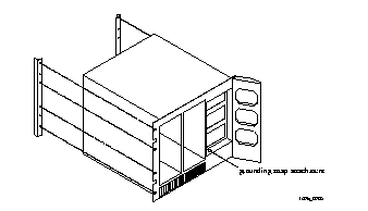 --Front Panel
- Figure 2-2 shows the proper places to attach a grounding wrist strap at the back of the chassis.
Figure 2-2 Grounding Strap Attachments--Rear Panel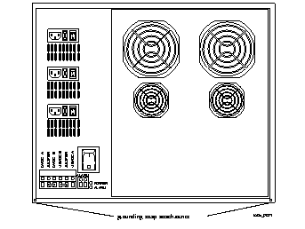
Power Safety Requirements
- Follow these safety requirements when installing and operating the PortMaster 4.
o AC Mains Cords . Be sure to use only the AC mains cord set supplied by your Lucent InterNetworking Systems authorized sales channel for the PortMaster 4. These cord sets are suitable for use in your region and comply with national and local safety requirements. Other cord sets must not be used.
¯ Mains cord must comply with the safety requirements of the national and international standards to which the equipment has been approved.
¯ Mains cord sets must also comply with the national and local safety requirements of any country for which the equipment is intended.
o Disconnection Devices. Because the AC mains cord sets are the primary devices for AC mains input connection and disconnection, ensure that all three sets are removed during PortMaster 4 disconnection to isolate mains power from the equipment.
o Socket Outlets. For safe connection and disconnection, ensure that three socket outlets are installed near the PortMaster 4 and are easily accessible.
o Single-Phase Equipment. Because the PortMaster 4 is intended for use on a single-phase supply rated at 100VAC to 240VAC, 47Hz to 63Hz, and 5/2A, ensure that all three socket outlets are provided from the same phase.
o Outside Plant Connections. Ensure that the PortMaster 4 is not set up for outside plant connections. The interfaces on the PortMaster 4 are not certified by the Network Equipment Building System (NEBS) for direct connection to outside plant.
o Canada . Ensure that bonding of the PortMaster 4 in Canada meets the requirements of Canadian standard C22.2 No. 04-M 1982, Bonding and Grounding of Electrical Equipment (Protective Grounding).
o Norway and Sweden. For installations in Norway or Sweden:
¯ Ensure that the PortMaster 4 is permanently connected to a safety earthing circuit via a suitable hardwired safety earthing conductor.
¯ Ensure that this earthing connector is connected to the chassis-mounted safety earthing connection, situated at the rear of the equipment, which is marked with the primary earth symbol. (IEC 417 No. 5019.)
o Japan DC Supply Input . The Safety Extra Low Voltage (SELV) limit in Japan is -45VDC. Ensure that the DC input to the PortMaster 4 does not exceed this limit in Japan. The PortMaster 4 functions normally with DC inputs in the range -38VDC to -55VDC.
Interconnection of Ports
Warning ¯  When connecting this equipment with other equipment or network interfaces, you must interconnect like ports only as designated in Table 2-1.
Table 2-1 Port Interconnection Requirements
|
Type of Circuit
|
Port Location
|
Port Descriptions
|
Network or Interconnecting Equipment Port
|
|---|
| SELV1
| Manager module
| Two console RS-232 ports
| SELV1
|
| SELV1
| Manager module
| Ethernet 10BaseT port
| SELV1
|
| SELV1
| Manager module
| Ethernet 10/100BaseT port
| SELV1
|
| SELV1
| Quad T1 line board
| Four T1 or ISDN Primary Rate Interface (PRI) lines
| TNV-12 or SELV1
|
| SELV1
| Tri E1 line board
| Three E1 or ISDN PRI lines
| TNV-12 or SELV1
|
| SELV1
| T3 Mux board
| Two T3 lines (one for transmitting, and one for receiving)
| TNV-12 or SELV1
|
| SELV1
| Standalone Ethernet line board
| One or two Ethernet 10/100BaseT ports
| SELV1
|
| SELV1
| STS-1 Mux board
| Two STS-1 lines (one for transmitting, and one for receiving)ports
| TNV-12 or SELV1
|
1. SELV --Safety Extra Low Voltage. A secondary circuit that is designed and protected so that, under normal and single fault conditions, its ages do not exceed a safe value.
2. TNV-1 --Telecommunication Network Voltage. A circuit whose normal operating voltages do not exceed the limits for an SELV circuit under normal operating conditions, on which overvoltages from telecommunication networks are possible.
Unpack the PortMaster 4
- To ensure the safety of the PortMaster 4 during shipment, the chassis, power supplies, boards, and modules are individually packaged.
Procedure
1. Turn the shipping box on its side, with the box opening perpendicular to the floor.
The PortMaster 4 chassis is in a cardboard tray inside the shipping box.
2. Slide the PortMaster 4 chassis out of the box, leaving it inside the cardboard tray.
3. Locate the handles on the side of the cardboard tray and use the handles to lift the PortMaster chassis to a rack.
Follow the procedure in the following section to attach the PortMaster 4 to a rack before installing any of its components.
4. Unpack and place the PortMaster 4 modules and boards on a flat, static-free work surface.
5. Ensure that you have at minimum the following equipment required for PortMaster 4 operation:
¯ One PortMaster 4 chassis.
¯ One AC power supply--unless -48VDC is provided externally. Additional AC power supplies can be added as necessary.
¯ One system manager module.
¯ One line board.
Attach the PortMaster 4 Chassis to a Rack
- Follow these instructions to attach the PortMaster 4 chassis to a rack.
Required Equipment
o Eight 12x24x1/2-inch Phillips pan head screws
o Phillips screwdriver
o 19-inch rack
Procedure
Caution ¯  Lucent recommends mounting the PortMaster 4 chassis with all slots empty and using three people to complete this task.
1. Using proper lifting procedures, position the PortMaster 4 chassis so that the front of the chassis is flush with the 19-inch rack.
2. Using the 8 Phillips screws, attach the PortMaster 4 chassis to the rack as shown in Figure 2-3.
Figure 2-3 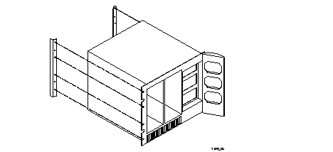 Attaching the PortMaster 4 to a Rack
Install a Cable Guide
- Follow these instructions to install a cable guide.
Required Equipment
o Three Phillips screws
o One Phillips screwdriver
o Three sets of washers (2 washers in each set)
o Cable guide (cable duct and cover)
Procedure
1. Line up the holes in the duct with the holes located above the slots on the chassis as shown in Figure 2-4.
¯ The hole on the left side of the chassis lines up with the third hole on the duct.
¯ The center hole in the chassis lines up with the seventh hole in the duct.
¯ The hole on the right side of the chassis lines up with the 11th hole in the duct.
Figure 2-4 Installing a Cable Guide
2. Using a Phillips screwdriver, attach the duct to the chassis as shown in Figure 2-4.
3. To install the cover on the cable guide, squeeze the duct fingers together with one hand while sliding the cover over the duct fingers with the other.
(Optional) Install AC Power Supplies
- The PortMaster 4 supports both AC and DC power connections and includes AC connections for three power supplies. The PortMaster 4 has three bays for two 400W switching power supplies plus a third 400W backup supply. The third power supply takes over if either of the other two power supplies fails. Each AC power supply has a fan. The DC connection has an A and B dual-feed arrangement. AC and DC connections can be used at the same time, with one as the primary power source and the other as a backup.
- Follow these instructions to install up to three AC power supplies in the PortMaster 4 chassis.
Procedure
Warning ¯  To avoid damaging the internal components of the PortMaster 4, follow antistatic precautions by wearing a grounding wrist strap. See "Grounding Wrist Strap Instructions" on page 2-3.
1. On the front of the PortMaster 4 chassis, open the door to the power supply bays.
2. Carefully slide the AC power supply into a bay in the front of the chassis as shown in Figure 2-5.
3. Ensure that the connectors on the power supply and the chassis slide together smoothly without force.
Figure 2-5 Installing a Power Supply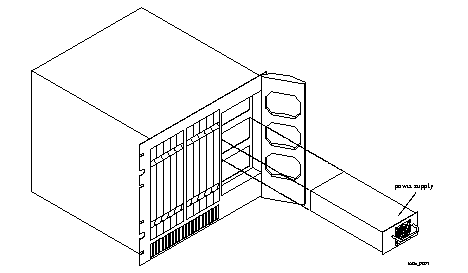
Caution ¯  Forcing a power supply into the chassis can damage the connectors.
4. Ensure that the power supply latches securely into the chassis with the latching lever (Figure 2-6).
Figure 2-6 Latching Lever on AC Power Supply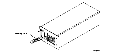
Install the Manager Module
- The PortMaster 4 is shipped with a system manager module that consists of a manager board and an Ethernet 10/100Mbps board. The manager board manages and administers the installed line boards. The manager board communicates with installed line boards at 155Mbps speeds through an embedded Asynchronous Transfer Mode (ATM) cell-switching network linked to the chassis' virtual backplane.
- Each manager module provides the following (see Figure 2-7):
- Follow these instructions to install the manager module.
Procedure
Warning ¯  To avoid damaging the internal components of the PortMaster 4, follow antistatic precautions by wearing a grounding wrist strap. See "Grounding Wrist Strap Instructions" on page 2-3.
1. Line up the edge of the module with the card guide in slot 4 (Figure 2-8).
Note ¯  The physical slots are numbered 0 through 9 from left to right. Although the Ethernet board in the manager module is physically installed in slot 4, it is monitored through virtual slot 10.
2. Insert the manager module in slot 4, gently guiding the module into the slot.
If you have trouble sliding the module into the card guide, gently wiggle it back and forth to help it slide in.
Figure 2-8 Installing the System Manager Module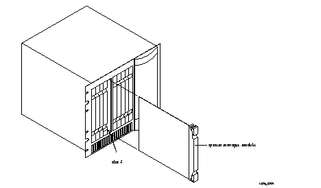
3. When the module is completely inserted in the slot, close the top and bottom tabs so they are flush with the face of the chassis.
Closing the tabs causes the module to connect with the backplane.
DIP Switch Settings
- The DIP switches on the manager module are located between Ether0 and Ether1 (see Figure 2-9). Each switch is off when turned to the left, and on when turned to the right.
- DIP switch 1 turned to the left forces the C0 port to have a configuration of 9600 baud, 8 bits, no parity, and 1 stop bit for use as a console port. When switch 1 is turned to the right, C0 can be configured as an asynchronous port.
- DIP switch 2 turned to the left sets the PortMaster 4 for netbooting. When switch 2 is turned to the right, the PortMaster 4 can boot normally.
- Figure 2-9 shows the DIP switch settings on the manager module.
Figure 2-9 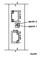 DIP Switches
Connect a Console
- Follow these instructions to connect a PC or terminal to the PortMaster 4 manager module for use as a console. You can use this connection to configure and manage the PortMaster 4.
Required Equipment
o If you are using a PC, a RJ-45-to-DB-25 console cable with a 25-to-9-pin female adapter (See "Console Cable" on page A-2 for more information.)
o PC or terminal
Procedure
1. Remove the cover from the cable guide if necessary.
2. Run the end of the cable with the RJ-45 connector through the cable guide duct until it is directly over the manager module.
3. Pull the end of the cable with the RJ-45 connector through the fingers of the cable guide duct as shown in Figure 2-10.
Figure 2-10 Pulling a Cable through the Cable Guide
4. Attach the RJ-45 connector to the C0 or C1 port of the manager module (see Figure 2-11).
Figure 2-11 Asynchronous Port on the System Manager Module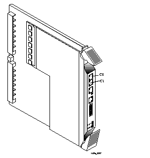
5. Attach the RS-232 end of the cable to a dumb terminal or computer running terminal emulation software.
6. If you have finished inserting modules and boards and connecting lines, replace the cable guide cover by squeezing the duct fingers together with one hand, and sliding the cover over the duct fingers with the other.
7. Ensure that DIP switch 1 on the manager module is turned to the left.
8. Set the PC or terminal to 9600 baud, 8 data bits, 1 stop bit, a parity of none, and software flow control on (XON/XOFF).
(Optional) Connect an External Modem
- Follow these instructions to connect an external modem for remote administration and troubleshooting.
Required Equipment
o RJ-45-to-RS-232 modem cable (See "Modem Cable" on page A-1 for more information.)
o External modem
Procedure
1. Remove the cover from the cable guide, if necessary.
2. Run the end of the cable with RJ-45 connector the through the cable guide duct until it is directly over the manager module.
3. Pull the cable through the fingers of the cable guide duct as shown in Figure 2-12.
Figure 2-12 Pulling a Cable through the Cable Guide
4. Attach the RJ-45 end of the cable to the C0 port of the manager module (see Figure 2-13).
Figure 2-13 Console Port on the System Manager Module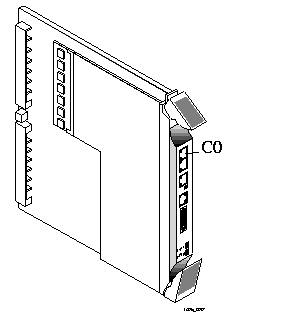
5. If you have finished inserting modules and boards and connecting lines, replace the cable guide cover by squeezing the duct fingers together with one hand, and sliding the cover over the duct fingers with the other.
6. Ensure that DIP switch 1 is turned to the right.
7. Attach the RS-232 end of the cable to the external modem.
Refer to the documentation that came with your external modem for information on how to attach the RS-232 cable.
Connect an Ethernet Cable
- The PortMaster 4 supports the following Ethernet connections:
Ethernet 10/100BaseT
- If you use only one Ethernet interface, Lucent recommends using Ether1. The Ether1 interface has the following characteristics:
- Resides on the Ethernet board, which receives power from the manager board. The Ethernet board and the manager board make up the manager module.
- Communicates with the manager board over the PortMaster 4's passive ATM backplane.
- Contains a CPU for inbound data and a CPU for outbound data.
- Remains active during low power or excessive heat conditions.
- Is generally used to configure network traffic.
- Follow these instructions to connect an Ethernet cable to the Ethernet 10/100BaseT interface.
- One of the following:
o Category 5 twisted pair cable, as specified by the EIA/TIA-568-B wiring standard, with an RJ-45 connector (See "RJ-45 Cable" on page A-2 and "Ethernet Cable Specifications" on page A-3 for more information.)
o MII cable with an MII connector
Procedure
1. Remove the cover from the cable guide, if necessary.
2. Run the cable through the cable guide duct until it is directly over the manager module.
3. Pull the cable through the fingers of the cable guide duct as shown in Figure 2-14.
4. Connect the cable to the RJ-45 or MII Ethernet 10/100BaseT interface (see Figure 2-15).
If both interfaces are connected, the system uses the MII by default.
5. If you have finished inserting modules and boards and connecting lines, replace the cable guide cover by squeezing the duct fingers together with one hand, and sliding the cover over the duct fingers with the other.
Figure 2-14 Pulling a Cable through the Cable Guide
Figure 2-15 Ethernet 10/100BaseT Interfaces on the Manager Module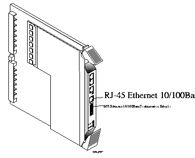
Ethernet 10BaseT
- Follow these instructions to connect an Ethernet cable to the Ethernet 10BaseT interface of the manager module.
Required Equipment
o Category 5 unshielded twisted pair cable, as specified by the EIA/TIA-568-A wiring standard, with an RJ-45 connector (See "RJ-45 Cable" on page A-2 and "Ethernet Cable Specifications" on page A-3 for more information.)
Procedure
1. Remove the cover from the cable guide, if necessary.
2. Run the cable through the cable guide duct until it is directly over the manager module.
3. Pull the cable through the fingers of the cable guide duct as shown in Figure 2-16.
Figure 2-16 Pulling a Cable through the Cable Guide
4. Connect the cable to the Ethernet 10BaseT interface (see Figure 2-17).
Figure 2-17 Ethernet 10BaseT Interface on the Manager Module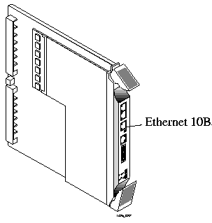
5. If you have finished inserting modules and boards and connecting lines, replace the cable guide cover by squeezing the duct fingers together with one hand, and sliding the cover over the duct fingers with the other.
Cover Empty Slots with Blank Modules
- When you have finished installing modules into the PortMaster 4, you must cover any empty slots with blank modules to promote air circulation and heat dissipation. A blank module has a blank faceplate and a short, blank board attached . If you order the PortMaster 4 with fewer than nine line boards, blank modules are included in the shipment.
- For example, if your PortMaster 4 chassis contains an STS-1 board in slot 0, a manager module in slot 4, and seven Quad T1 boards in slots 1 through 3 and 6 through 9, you must insert blank modules in slots 5 and 10.
Required Equipment
o Blank modules
Procedure
1. Line up the edge of the blank module with the card guide in an empty slot.
2. Gently guide the blank module into the slot.
If you have trouble sliding the module into the card guide, gently wiggle it back and forth to help it slide in.
3. When the module is completely inserted in the slot, close the top and bottom tabs so they are flush with the face of the chassis.
Closing the tabs secures the module in the chassis.
4. Repeat the procedure until all empty slots are covered.
[Top] [Table Of Contents] [Prev] [Next] [Index]
5 out of 16 total pages
spider@livingston.com
Copyright © 1999, Lucent Technologies. All rights
reserved.
![]() (DC models only) Before working on equipment that is connected to power lines, remove jewelry such as rings, necklaces, and watches. Metal objects will heat up when connected to power and ground and can cause serious burns or weld the metal object to the terminals.
(DC models only) Before working on equipment that is connected to power lines, remove jewelry such as rings, necklaces, and watches. Metal objects will heat up when connected to power and ground and can cause serious burns or weld the metal object to the terminals.
 --Front Panel

 Attaching the PortMaster 4 to a Rack


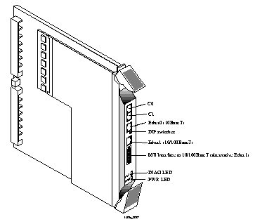

 DIP Switches


