[Top] [Table Of Contents] [Prev] [Next] [Index]
7 out of 16 total pages
Core Troubleshooting and Maintenance 4
- This chapter gives the following troubleshooting and maintenance instructions for core PortMaster 4 hardware:
Troubleshooting LED Behavior on the Manager Module
- Figure 4-1 identifies the manager module's LED problem-indicating behavior, possible causes of the behavior, and potential solutions.
Table 4-1 Hardware Problems and Solutions on the Manager Module
|
LED Behavior
|
Possible Cause
|
Possible Solution
|
|---|
| All LEDs fail to light.
| Power is not present.
| Check the power switch, power cable, outlet, and fuse. For instructions on checking and changing the fuse in the AC version, see "Replacing a Fuse" on page 4-10.
Contact Lucent InterNetworking Systems Technical Support if power is not present on the DC version.
|
| Amber DIAG LED on the manager module does not light.
| Board malfunction.
| Contact Lucent InterNetworking Systems Technical Support.
|
| During startup, the DIAG LED on the manager module fails to light, stays lit, or blinks three times per second continuously.
| A hardware problem has occurred.
| Contact Lucent InterNetworking Systems Technical Support.
|
| During startup, the DIAG LED on the manager module blinks once per second for more than a minute.
|
· DIP switch 2 is turned to the left and no boot server is present.
· Nonvolatile RAM contents are corrupt.
|
· If no boot server is available, verify that DIP switch 2 is turned to the right and reboot; otherwise, see the network booting procedure in the PortMaster Troubleshooting Guide.
· If nonvolatile RAM contents are corrupt, follow the PortMaster Troubleshooting Guide procedure for network booting and rewriting the contents of nonvolatile RAM.
|
| Immediately after booting, the DIAG LED on the manager module stays solidly lit or does not light.
This behavior does not refer to the boot sequence, during which the DIAG LED is not lit for between 5 and 7 seconds.
| A component might have loosened during shipping.
| Remove the manager module from the PortMaster 4 chassis and verify the following:
· The SIMM is firmly seated.
· The nonvolatile RAM is firmly in place.
If all items have been verified and the problem is not fixed, refer to "Observing Boot Messages" on page 4-3, and boot in console mode. If the boot messages do not suggest a solution, record the information and contact Lucent InterNetworking Systems Technical Support.
|
| During operation, the DIAG LED on the manager module stays solidly lit or does not light.
| A hardware problem might have been caused by an external device.
| If the LED stays solidly lit or does not light after you have removed all external devices, contact Lucent InterNetworking Systems Technical Support.
|
| No console login prompt is displayed.
| Terminal settings are incorrect or a connection or cable is inoperable.
|
· Verify terminal settings of 9600 baud, 8 data bits, 1 stop bit, a parity of none, and software control on (XON/XOFF).
· Verify that DIP switch 1 is turned to the left.
· Verify that you have a working console (null modem) cable and that it is properly connected at both ends. For cable information see "Console Cable" on page A-2.
|
| Link (green) LED on an Ethernet interface is not lit when connected to an Ethernet hub.
| There is no link integrity.
| Check the connection to the hub.
|
| Network (amber) LED on an Ethernet interface is solidly lit.
| Heavy traffic can cause the network LED to blink so rapidly that it appears to be solidly lit.
However; If packets cannot be passed, you might have an incorrectly cabled network.
| Verify that the network cabling is correct.
|
| Network (amber) LED on an Ethernet interface is not lit.
| If the PortMaster 4 is not receiving or sending traffic, the network LED is not lit.
| Verify that the network cabling is correct.
|
| An undefined problem occurred at startup, but the cause cannot be determined from LED behavior.
| Refer to the solution column.
| Try booting in console mode, and observe the boot messages. See "Observing Boot Messages" on page 4-3. If the boot messages do not suggest a solution, record the information and contact Lucent InterNetworking Systems Technical Support.
|
Observing Boot Messages
- If you are having difficulty booting the PortMaster 4 and are unable to isolate the problem by observing LED behavior, boot the PortMaster 4 in console mode and check the boot messages.
- Follow these instructions to check boot messages:
1. Set up a console connection to the manager module (see "Connect a Console" on page 2-13).
2. Turn on power (see "Turn On Power" on page 3-2).
3. Observe the boot messages displayed on the console screen.
Note ¯  Boot messages vary slightly, depending on the version of the nonvolatile RAM and ComOS and whether line boards are installed.
- The following listing displays a normal boot process for a PortMaster 4:
PM4 manager prom 1.4
Testing System Clock....
Sizing System Memory... 16MB
CPU Type.... 486DX5-133
Starting FLASH Boot.....
Flash Memory ... Am29F016 8192K
16384 flash copy complete
Verifying Loader Module Checksum...
Starting Loader ...
Loading kernel... 1184788 bytes
Testing High Memory ... . 16384K
Found Slot ID 5
Setting up ACC 2188 PCI Controller
Found 1024K PCI Memory at 0x20000000
Testing PCI Memory block 0x20000000-0x200fffff ...Passed
Total of 1024K PCI Memory Ready
block_alloc: cpu<0> control 002e3f70 free_count<460>
Setting up ATM SAR Chip (TC35856-BF), Reverse_Utopia
Testing SAR SRAM Memory ...128K
Scheduler Process: 133250
Flash Memory ... Am29F016 8192K
Flash type Am29F016 with 8192K of memory in 128 cells and 8064 nodes
Found 12 ports....
board: init Slot4 12 0 0 0 0 0 0 1
e_loopback_test: packet buffer at 200d0080
ether0 active ... PCI-Master
Resetting Switch Matrix
Setting up MMC ATM Switch Matrix
Switch fabric Management connections ... Ready
Switch fabric Socket connections ... Ready
Switch fabric Data connections ... Ready
MMC ATM Switch is ready
Running ComOS...
PortMaster Console login: board: init Slot10 0 0 0 0 0 0 0 1
board
|
Note ¯  ComOS 4.1 enables you to display a history of reboots on the manager module and line boards. From the console, type in the command show bootlog . If a crash occurs, the stack trace is saved. The boot log is stored in the nonvolatile RAM file system (Flash memory) as a 64KB file. This file can be erased with the erase file bootlog command. For more information, see the PortMaster 4 Configuration Guide and PortMaster 4 Command Line Reference .
-
-
Table 4-2 Interpreting Diagnostic Boot Messages
Field
|
Possible Message
|
Explanation
|
|---|
| PM4 manager prom
| N
| Version number of the installed boot PROM.
|
| Testing System Clock
| ERROR
| This error indicates a boot failure. Record all information to this point and contact Lucent InterNetworking Systems Technical Support.
|
| Sizing System Memory
| ERROR at failed memory address.
| This error indicates a boot failure. Record all information to this point and contact Lucent InterNetworking Systems Technical Support.
|
| CPU Type
| 486DX5-133
| The type of CPU installed.
|
| Starting FLASH Boot
| N/A
| N/A
|
| Flash Memory
| Am29F016 8192K
| Nonvolatile RAM brand name and size in kilobytes.
|
| flash copy complete
| 16384
| Counter for nonvolatile RAM bytes transferred to dynamic RAM. If the counter freezes, record all information to this point and contact Lucent InterNetworking Systems Technical Support.
|
| Verifying Load Module Checksum
| Invalid Length for Flash at RAM
address.
| This error indicates a boot failure. Record all information to this point and contact Lucent InterNetworking Systems Technical Support.
|
| Starting Loader
| N/A
| N/A
|
| Loading kernel
| 1184788
| Size of kernel image in bytes.
|
| Testing High Memory
| ERROR at failed memory address
| This error indicates a boot failure. Record all information to this point and contact Lucent InterNetworking Systems Technical Support.
|
| Found Slot ID 5
|
|
|
Setting up ACC 2188 PCI Controller
Found 1024K PCI Memory at 0x20000000
Testing PCI Memory block 0x20000000-0x200fffff ...Passed
Total of 1024K PCI Memory Ready
block_alloc: cpu<0> control 002e3f70 free_count<460>
|
| PCI memory has been correctly set up.
|
| Setting up ATM SAR Chip (TC35856-BF), Reverse_Utopia
Testing SAR SRAM Memory ...128K
|
| Segmentation and reassembly (SAR) chip is running. The SAR controls the ATM backplane.
|
| Scheduler Process: 133250
|
| For Lucent InterNetworking Systems engineering use only.
|
| Found x ports
| Integer between 2 and 864
| Number of ports found, including C0 and C1. The total number of ports found depends on the number of installed boards.
|
| board: init Slot4 12 0 0 0 0 0 0 1
|
|
|
| ether0 active
| PCI-Master
| Ethernet interface found.
|
Resetting Switch Matrix
Setting up MMC ATM Switch Matrix
Switch fabric Management connections ... Ready
Switch fabric Socket connections ... Ready
Switch fabric Data connections ... Ready
MMC ATM Switch is ready
|
| ATM matrix has been reset.
|
| Running ComOS
| N/A
| If the system becomes suspended at this point and does not print the next message, the configuration nonvolatile RAM (NVRAM) has been corrupted. Refer to the PortMaster Troubleshooting Guide for instructions on nonvolatile RAM recovery.
|
| PortMaster Console login:
| N/A
| System is up and running.
|
| board: init
| Slot10...
| Installed boards are identified and initialized.
|
Use Figure 4-2 to interpret possible diagnostic boot messages.
Replacing a Failed Module or Line Board
- Follow these steps to replace a failed manager module, Ethernet module, or line board.
Warning ¯  To avoid damaging the internal components of the PortMaster 4, follow antistatic precautions by wearing a grounding wrist strap. See "Grounding Wrist Strap Instructions" on page 2-3.
Caution ¯  The system manager module is currently not hot-swappable, and its disconnection stops the PortMaster 4 from working. However, you can replace a failed manager module without shutting down power to the PortMaster 4.
1. Do one of the following:
¯ If you are replacing the manager module that is still running, log out from the PortMaster 4.
¯ If you are replacing an Ethernet module or line board, enter the following command to turn off power to the board:
Command> set Slot0 off
Replace Slot0 with the number of the slot in which the board is installed.
2. Disconnect any cables from the failed module or board.
3. Open the top and bottom tabs on the failed module or board, and remove it from the slot in the PortMaster 4 chassis.
4. Line up the edge of the new module or board with the card guide in the same slot (see Figure 4-1).
The manager module must be inserted into slot 4.
5. Gently guide the new module or board into the slot.
If you have trouble sliding the module or board into the card guide, gently wiggle it back and forth to help it slide in.
Figure 4-1 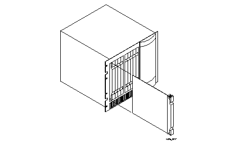 Installing a New Module or Board
6. When the module or board is completely inserted into the slot, close the top and bottom tabs so they are flush with the face of the chassis.
Closing the tabs connects the module or board to the backplane.
7. Reconnect any cables you disconnected in Step 2.
8. Do one of the following:
¯ If you are replacing a failed Ethernet module or line board, enter the following command to turn on power to the board:
Command> set Slot0 on
Replace Slot0 with the number of the slot in which the board is installed.
9. If you are replacing a manager module, log back into the PortMaster 4.
Replacing a Failed AC Power Supply
- In the event of a power supply failure, the PortMaster 4 manager module shuts down boards if the power requirement begins to exceed the available power. Boards are shut down in numeric order, with the highest-numbered slots being shut down first.
- Follow these steps to replace a failed AC power supply.
Required Equipment
o Replacement power supply
Procedure
Warning ¯  To avoid damaging the internal components of the PortMaster 4, follow antistatic precautions by wearing a grounding wrist strap. See "Grounding Wrist Strap Instructions" on page 2-3.
1. Turn off the switch and unplug the power cord at the failed AC power supply.
2. On the front of the PortMaster 4 chassis, open the door to the power supply bays.
3. Pull down the latching lever on the failed AC power supply (Figure 4-2), and carefully slide the failed power supply out of the PortMaster 4 chassis (Figure 4-3).
Figure 4-2 Latching Lever on AC Power Supply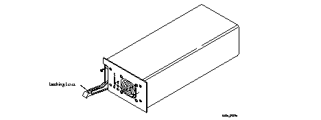
Figure 4-3 Installing a Power Supply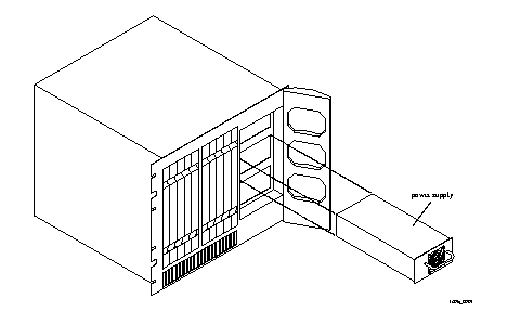
Caution ¯  Forcing a power supply into the chassis can damage the connectors.
4. Carefully slide the new AC power supply into a bay in the front of the chassis as shown in Figure 4-3.
5. Ensure that the connectors on the power supply and the chassis slide together smoothly without force.
6. Ensure that the power supply latches securely into the chassis with the latching lever (Figure 4-2).
7. Reattach the power cord to the power supply and turn the power on.
If necessary, the PortMaster 4 automatically turns boards on as power becomes available.
Replacing a Fuse
- If your PortMaster 4 loses power while connected to an active power source, check the fuse.
- Follow these instructions to check and replace the fuse in the PortMaster 4.
Required Equipment
o 5/32-inch flathead screwdriver
o 250V, 2A fuse (AC version)
Procedure
1. Turn the power switch(es) off and disconnect the PortMaster 4 from all power sources.
If you are using more than one power supply, you must disconnect all power supplies before replacing the fuse.
2. Detach the power cord(s) from the PortMaster 4.
3. Insert a 5/32-inch flathead screwdriver between the fuse door and the chassis, and gently pull the fuse door open (Figure 4-4).
Figure 4-4 Opening the Fuse Door
4. If the white outer coating of the fuse is discolored (burned), replace the fuse.
The fuse can be inserted from either end.
5. Press the fuse door shut until it clicks.
6. Reconnect the power cord(s) to the PortMaster 4.
7. Turn the power switch(es) on.
Replacing a Failed Fan
- The PortMaster 4 has two 48VDC fans rated at 100CFM at 0 inches of water static pressure and two 48VDC fans rated at 50CFM at 0 inches of water static pressure.
- In the event that a fan fails, the PortMaster 4 manager module shuts down operations as the temperature in the unit exceeds safe limits.
- Follow these steps to replace a failed fan.
Required Equipment
o Phillips screwdriver
o Replacement fan
Caution ¯  Wear a grounding strap when handling the internal components of the PortMaster 4.
1. Remove the four screws that secure the back panel of the PortMaster 4 chassis (Figure 4-5).
When the screws are removed, the back panel swings out from the chassis to reveal the fan assembly (Figure 4-6).
Figure 4-5 Screws Securing Back Panel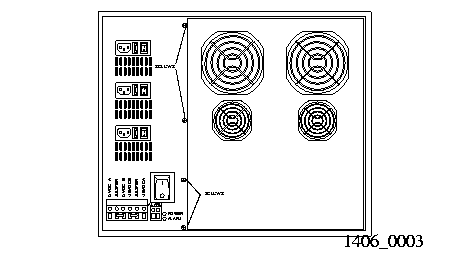
Figure 4-6 Fan Assembly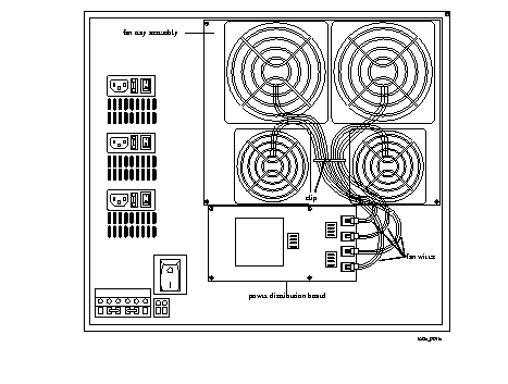
2. Unscrew the four screws located on the corners of the failed fan.
3. Remove the wires of the failed fan from the clip.
4. Remove the fan wires from the power distribution board.
5. Remove the failed fan from the fan assembly tray.
6. Using the four fan screws, secure the replacement fan to the fan tray.
7. Reconnect the fan wires into the appropriate receptacle on the power distribution board.
Fan wires are labeled 1 through 4 . The receptacles are labeled J1 through J4 . Connect wires labeled 1 into the receptacle labeled J1 , connect wires labeled 2 into the receptacle labeled J2 , and so on.
8. Fit the back panel under the groove on the right side of the chassis.
9. Secure the left side of the panel with the four back panel screws.
Replacing the Fan Power Distribution Board
- The fans in a PortMaster 4 are connected to a fan power distribution board located below the fans. A fan power distribution board might need to be replaced if
- Follow these steps to replace the fan power distribution board.
Warning ¯  You must wear a grounding strap when working with the electronic components of the PortMaster 4. Failure to do so could result in damage to the electronic components.
1. Turn all power switches off, and disconnect the PortMaster 4 from the power source.
2. Unscrew the four screws that secure the rear panel of the PortMaster 4 chassis.
When the screws are removed, the back cover swings out from the chassis.
3. Disconnect the fan wires from the power distribution board (Figure 4-6).
4. Unscrew the four screws on the corners of the power distribution board.
5. Disconnect the power distribution board and remove it from the rear of the chassis.
If the power distribution board is not easy to remove at this point, ensure that Steps 2 through 4 were performed correctly.
6. Plug the new power distribution board into the base.
7. Using the four screws, attach the power distribution board to the rear of the PortMaster 4 chassis.
8. Connect the fan wires into the power distribution board.
Connect wires labeled 1 into the receptacle labeled J1 , connect wires labeled 2 into the receptacle labeled J2 , and so on.
9. Fit the rear panel under the groove on the right side of the chassis.
10. Secure the left side of the panel with the four back panel screws.
11. Reconnect the power source(s) and turn on power to the PortMaster 4.
Installing Memory on the Manager Module
- Follow these instructions to do the following:
- Upgrade or replace a single inline memory module (SIMM) of dynamic RAM (DRAM)
- Replace the nonvolatile RAM--also known as a dual inline memory module (DIMM)
Upgrading or Replacing SIMMs
- The manager module ships with one 16MB socketed single inline memory module (SIMM) of dynamic RAM, upgradable to 32MB.
Note ¯  The PortMaster 4 does not support extended data output (EDO) dynamic RAM.
Required Equipment
o One socketed SIMM with 72 pins, 60-nanosecond-or-better speeds, and no parity
Procedure
Warning ¯  To avoid damaging the internal components of the PortMaster 4, follow antistatic precautions by wearing a grounding strap. See "Grounding Wrist Strap Instructions" on page 2-3.
1. Ensure that all power switches are turned off and that the PortMaster 4 is disconnected from all power sources.
2. Disconnect all connectors from the manager module.
3. Open the top and bottom tabs on the module, and remove it from the slot in the PortMaster 4 chassis (Figure 4-7).
Figure 4-7 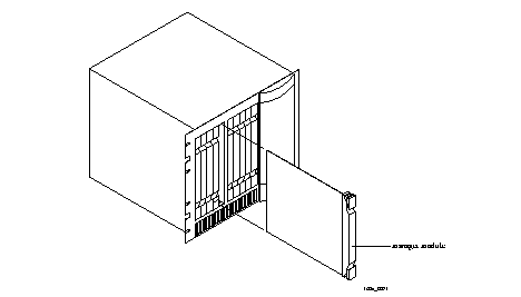 Removing a Manager Module
4. Locate the SIMM socket.
When the front of the manager module is facing you, the SIMM socket is in the back right quadrant of the module, located next to the socketed nonvolatile RAM. The SIMM socket is about 1 inch wide and 4 inches long.
5. Pull the levers on either side of the SIMM socket away from the SIMM.
If the SIMM does not pop up on its own, gently pull it up to about a 45-degree angle.
6. Pull the old SIMM out of its socket and put it in a static-free bag.
7. Insert the new SIMM into the SIMM socket.
The SIMM has pin 1 on the left side. Generally, 72-pin SIMMs have a notch that allows them to be inserted only one way. Make sure that the SIMM is completely pushed into the socket.
8. With even pressure, push down on the SIMM until the side levers engage.
The holes on either side of the SIMM must line up with holes in the SIMM socket.
9. Carefully reinstall the module into the PortMaster 4, being careful to close the top and bottom tabs and reconnect all connectors.
See "Install the Manager Module" on page 2-10 for detailed instructions if necessary.
10. Reconnect power sources, turn on the power, and log back in to the PortMaster 4.
Replacing the Nonvolatile RAM (DIMM)
- Use the following procedure to replace the nonvolatile RAM installed on the manager module of the PortMaster 4.
Warning ¯  To avoid damaging the internal components of the PortMaster 4, follow antistatic precautions by wearing a grounding wrist strap. See "Grounding Wrist Strap Instructions" on page 2-3.
Required Equipment
o One socketed 8MB nonvolatile RAM card, also known as a DIMM
Procedure
1. Ensure that all power switches are turned off and that the PortMaster 4 is disconnected from all power sources.
2. Disconnect all connectors from the manager module you are upgrading.
3. Open the top and bottom tabs on the manager module, and remove it from the slot in the PortMaster 4 chassis.
4. Locate the DIMM on the manager module.
When the back of the manager module is facing you, the DIMM is located towards the back left quadrant of the module. The DIMM is about 2-1/2 inches long and 1 inch wide.
5. If the DIMM is partially covered by the SIMM, remove the SIMM.
See "Upgrading or Replacing SIMMs" on page 4-15 for instructions.
6. Locate the small plastic levers on either side of the DIMM socket, and gently pull them away from the DIMM.
Use care because these levers are fragile and break easily. If the DIMM does not pop up on its own, pull it up to about a 45-degree angle.
7. Remove the old DIMM from its socket.
8. Slide the new DIMM into the socket, gold fingers toward the socket, at a 45-degree angle.
The DIMM fits into the socket only one way. The DIMM is completely inserted when the gold fingers are no longer showing.
9. Push the DIMM down until the side levers lock it in place.
10. Reinstall the SIMM, if necessary.
See "Upgrading or Replacing SIMMs" on page 4-15 for instructions.
11. Carefully reinstall the manager module into the PortMaster 4, being careful to close the top and bottom tabs and reconnect all connectors.
See "Install the Manager Module" on page 2-10 for detailed instructions if necessary.
12. Reconnect power sources, turn on the power, and log back in to the PortMaster 4.
[Top] [Table Of Contents] [Prev] [Next] [Index]
7 out of 16 total pages
spider@livingston.com
Copyright © 1999, Lucent Technologies. All rights
reserved.
![]() Boot messages vary slightly, depending on the version of the nonvolatile RAM and ComOS and whether line boards are installed.
Boot messages vary slightly, depending on the version of the nonvolatile RAM and ComOS and whether line boards are installed.
![]() ComOS 4.1 enables you to display a history of reboots on the manager module and line boards. From the console, type in the command show bootlog . If a crash occurs, the stack trace is saved. The boot log is stored in the nonvolatile RAM file system (Flash memory) as a 64KB file. This file can be erased with the erase file bootlog command. For more information, see the PortMaster 4 Configuration Guide and PortMaster 4 Command Line Reference .
ComOS 4.1 enables you to display a history of reboots on the manager module and line boards. From the console, type in the command show bootlog . If a crash occurs, the stack trace is saved. The boot log is stored in the nonvolatile RAM file system (Flash memory) as a 64KB file. This file can be erased with the erase file bootlog command. For more information, see the PortMaster 4 Configuration Guide and PortMaster 4 Command Line Reference .
 Installing a New Module or Board


 Removing a Manager Module