Note ¯ Because ![]() the Ethernet board is hot-swappable, you can install it while the PortMaster 4 is turned on and running.
the Ethernet board is hot-swappable, you can install it while the PortMaster 4 is turned on and running.
Although physically installed in slot 3, the Ether31 interface is monitored and reset thorough virtual slot 11.
Note ¯ Because ![]() the Ethernet board is hot-swappable, you can install it while the PortMaster 4 is turned on and running.
the Ethernet board is hot-swappable, you can install it while the PortMaster 4 is turned on and running.
Warning ¯ ![]() To avoid damaging the internal components of the PortMaster 4, follow antistatic precautions by wearing a grounding wrist strap. See "Grounding Wrist Strap Instructions" on page 2-3.
To avoid damaging the internal components of the PortMaster 4, follow antistatic precautions by wearing a grounding wrist strap. See "Grounding Wrist Strap Instructions" on page 2-3.
1. Line up the edge of the board with the card guide in the appropriate slot.
¯ If you are installing a single-interface Ethernet board, you can use any slot except slot 4 (Figure 7-1).
¯ If you are installing a dual-interface Ethernet module, you must install it in slot 3.
Slots are numbered 0 through 9 from left to right. Slot 4 is reserved for the manager module.
Figure 7-1 Installing a Standalone Ethernet Board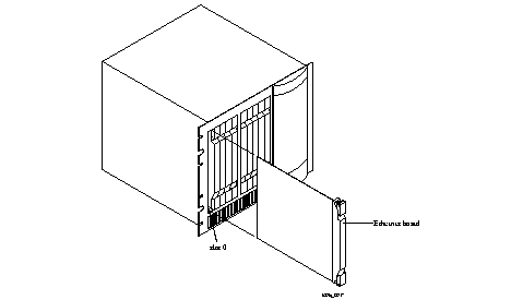
2. Insert the board in the slot and gently guide it into the slot.
If you have trouble sliding the board into the card guide, gently wiggle it back and forth to help it slide in.
3. When the board is completely inserted in the slot, close the top and bottom tabs so they are flush with the face of the chassis.
Closing the tabs causes the board to connect with the backplane.
4. After you finish installing boards or modules in the PortMaster 4, ensure that every slot contains either a working board or blank board.
Figure 7-2 Single-Interface and Dual-Interface Ethernet Board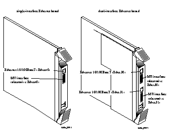 s
s
o Category 5 twisted pair cable, as specified by the EIA/TIA-568-B wiring standard, with an RJ-45 connector (See "RJ-45 Cable" on page A-2 and "Ethernet Cable Specifications" on page A-3 for more information.)
1. Remove the cover from the cable guide, if necessary.
2. Run the cable through the cable guide duct until it is directly over the standalone Ethernet board or module.
3. Pull the cable through the fingers of the cable guide duct as shown in Figure 7-3.
Figure 7-3 Pulling a Cable through the Cable Guide
4. Connect the cable to the Ethernet RJ-45 connector or MII connector (see Figure 7-2).
5. Verify the following LED behavior:
a. The PWR LED at the bottom of the board or module is solidly lit.
b. The amber DIAG LED at the bottom of the board blinks three times per second during startup and then stays solidly lit with a 1-second interruption every 5 seconds.
DIAG LED behavior might vary according to the version of ComOS you are running.
c. The green link LED next to the RJ-45 interface is solidly lit for each Ethernet connection.
d. The amber network LED next to the RJ-45 interface blinks when Ethernet traffic is present.
See "Troubleshooting LEDs on a Standalone Ethernet Board" on page 7-5 if any LED fails to behave properly.
6. If you have finished inserting modules and boards and connecting lines, replace the cable guide cover by squeezing the duct fingers together with one hand, and sliding the cover over the duct fingers with the other.
| All LEDs fail to light. | Power is not present. | Check the power switch, power cable, outlet, and fuse. For instructions on checking and changing the fuse in the AC version, see "Replacing a Fuse" on page 4-10. Contact Lucent InterNetworking Systems Technical Support if power is not present on the DC version. |
| Amber DIAG LED on a standalone Ethernet board does not light. | Board malfunction. | Contact Lucent InterNetworking Systems Technical Support. |
| During startup, the DIAG LED on a standalone Ethernet board fails to light, stays lit, or blinks three times per second continuously. | A hardware problem has occurred. | Contact Lucent InterNetworking Systems Technical Support. |
| During operation, the DIAG LED on a standalone Ethernet board stays solidly lit or does not light. | A hardware problem might have been caused by an external device. | If the LED stays solidly lit or does not light after you have removed all external devices, contact Lucent InterNetworking Systems Technical Support. |
| Link LED on a standalone Ethernet board is not lit when connected to a 10/100BaseT Ethernet hub. | There is no link integrity. | Check the connection to the hub. |
| Network (amber) LED on a standalone Ethernet board is solidly lit. | Heavy traffic can cause the network LED to blink so rapidly that it appears to be solidly lit. However, if packets cannot be passed, you might have an incorrectly cabled network. | Verify that the network cabling is correct. |
| Network (amber) LED on a standalone Ethernet board is not lit. | If the PortMaster 4 is not receiving, or sending traffic, the network LED is not lit. | Verify that the network cabling is correct. |
| An undefined problem occurred at startup, but the cause cannot be determined from LED behavior. | Refer to the solution column. | Try booting in console mode, and observe the boot messages. See "Observing Boot Messages" on page 4-3. If the boot messages do not suggest a solution, record the information and contact Lucent InterNetworking Systems Technical Support. |