[Top] [Table Of Contents] [Prev] [Next] [Index]
12 out of 16 total pages
 

STS-1 Multiplexer (Mux) Boards   9


  This chapter provides installation, configuration, troubleshooting, and maintenance information for the STS-1 Mux boards.
 

       STS-1 Mux Board Description

  The Synchronous Transport Signal level 1 (STS-1) Mux board is designed to integrate a PortMaster 4 into a switching installation of a telecommunications service provider. STS-1 is the basic signal for the Synchronous Optical Network (SONET), defined by the Bellcore standard GR-253-CORE.
  The STS-1 signal uses synchronous byte-interleaved multiplexing to transfer its payload. The payload is the portion of the SONET signal that is available to carry DS-1 signals. The payload contents of the STS-1 circuit consists of the STS path overhead (POH) and a synchronous payload envelope (SPE) from a virtual tributary (VT). The STS POH is used to communicate the location where the payload is mapped to, and the STS-1 SPE is used to deliver the payload. STS-1 circuits operate at 51.840Mbps, carrying 28 DS-1 signals in the form of 28-byte mapped VTs. The interleaved VTs travel at 1.728Mbps.
  Each DS-1 is demultiplexed within the STS-1 board at the VT-1.5 rate of 1.728Mbps, using information from the SPE to map each DS-1 signal onto the PortMaster 4 ATM backplane. Four DS-1 channels are mapped to each Quad T1 board. To demultiplex all 28 DS-1 signals, a PortMaster 4 must have seven Quad T1 boards installed.
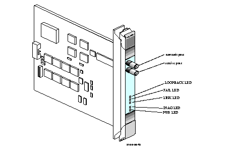
  The physical interface on the STS-1 board consists of two 75-ohm coaxial BNC connectors that provide one line for transmitting and one for receiving.

  Note ¯ Lucent recommends that you use the STS-1 Mux board with external clocking. Because the STS-1 signal is synchronous, all clocks in the system have the same constant frequency. The STS-1 rate remains at 51.84Mbps, allowing many synchronous STS-1 signals to be stacked together when multiplexed.
 

       Installing an STS-1 Mux Board

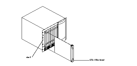
  Follow these instructions to install an STS-1 Mux board.

  Note ¯ Because the STS-1 Mux board is hot-swappable you can install an STS-1 Mux board while the PortMaster 4 is turned on and running.


       Connecting an STS-1 Line

  Follow these instructions to connect an STS-1 line.

  Note ¯ This procedure does not cover instructions for provisioning the switch or the data networks to support the PortMaster 4. For more specific information on how to provision your data network or switch, contact your telecommunications service provider.


       Configuring an STS-1 Mux Board

  Use the commands in Table 9-1 to configure the STS-1 board and the Quad T1 boards to enable the transport of DS-1 T1 circuits over the PortMaster 4 ATM backplane. To fully demultiplex an STS-1 circuit you must have seven Quad T1 boards installed.
  For more information about configuration settings, refer to the PortMaster 4 Configuration Guide  and PortMaster 4 Command Line Reference. 

  Note ¯ To activate the STS-1 Mux board, you must first configure Ether0 or Ether1 with an IP address.

  Table 9-1 shows the STS-1 configuration commands.

  Table 9-1 STS-1 Mux Board Configuration Commands  


  Action

  Command Syntax

  Event

 Determine slot numbers.

  · Command> show slots

 This command identifies all boards loaded in the PortMaster 4, and determines each of their slot locations.
 Configure the STS-1 clock source.

  · Command> set view 0 

 To configure a specific board, you must enter the specific slot number in the set view  command.
 

  · Command 0> set mux line-clock external 

 Set the STS-1 clock source to external --the default setting.
 Configure each Quad T1 board.

  · Command 0> set view 1 

 For each Quad T1 board, set the slot where it is installed--for example, slot 1.
 

  · Command 1> set line0 clock backplane

  · Command 1> set line0 source 0:1

 Then assign a clock source to Quad T1 lines 0, 1, 2, and 3 on the Quad T1 boards from the ATM backplane of the PortMaster 4. Finally, map each T1 line for multiplexing to a DS-1 channel between 1 and 28 on the STS-1 Mux board. Each Quad T1 line is assigned a DS-1 T1 circuit from the STS-1 Mux board in slot 0.
 

  · Command 1> set line1 clock backplane 

  · Command 1> set line1 source 0:2 


  · Command 1> set line2 clock backplane

  · Command 1> set line2 source 0:3 


  · Command 1> set line3 clock backplane

  · Command 1> set line3 source 0:4

 
 Save settings and reboot.

  · Command 1> set view 0 

 You can save configuration settings and reboot the PortMaster 4 from any slot.
 

  · Command 1> save all 

 This command saves all  configuration settings into nonvolatile RAM on the system manager module.
 

  · Command 1> reboot

 To make all configurations active, a reboot is required.
 Perform loopback testing.

  · Command 1> set view 0 

 Set the view to the STS-1 board.
 

  · Command 0> set mux line-loop auto |on |off 

 This command initiates a loopback from the STS-1 board to the STS-1 circuit source to help determine the state of the STS-1 circuit.
 

  · Command 0> set mux channel-loop  Channel auto |on |off 

 This command initiates a loopback from the STS-1 board for a specific DS-1 circuit back to the STS-1 circuit source. Replace Channel with the number of the DS-1 channel--between 1 and 28.
 Debug the configuration.

  · Command 0> set debug mux 

 This command activates the output of the STS-1 debug information.
 

  · Command 0> set console

 This command directs all debug output to the command line screen of your session.
 

  · Command 0> set debug off

 This command turns debug mode off.
 

  · Command 0> reset console 

 This command redirects all debug output to null.
 

       Troubleshooting LED Behavior on an STS-1 Mux Board

  Table 9-2 identifies problems-indicating LED behavior on an STS-1 Mux board, possible causes of the behavior, and possible solutions

  Table 9-2 Hardware Problems and Solutions on an STS-1 Mux Board  


  Problem

  Possible Cause

  Possible Solution

 The green LINK LED is lit with no line connection.  Possible hardware failure.  Contact Lucent Technical Support.
 All LEDs fail to light.  Power is not present.  Check to make sure the power switch is turned on, the power cable is connected, the boards are properly seated, and the fuse functions.  For instructions on checking and changing the fuse, see "Replacing a Fuse" on page 4-10.  If unable to diagnose contact Lucent Technical Support.
 Amber DIAG LED on a STS-1 Mux board does not light.  STS-1 Mux board malfunction.  Contact Lucent Technical Support.
 During startup, the DIAG LED on an STS-1 Mux board fails to light, stays lit, or blinks three times per second continuously.  A hardware problem has occurred.  Contact Lucent Technical Support.
 During operation, the DIAG LED on an STS-1 Mux board stays solidly lit or does not light.  A hardware problem might have been caused by an external device.  If the LED stays solidly lit or does not light after you have removed all external devices, contact Lucent Technical Support.
 The amber LOOPBACK LED is lit.  The STS-1 line is in loopback.  If the loopback setting is in error, use the set mux line-loop off  command to clear the loopback. See the PortMaster 4 Command Line Reference for more information.
 The green FAIL LED is lit.  No line is connected.  Check that the cables are securely fastened to the ports.
 The amber LINK LED is not lit.  There is no STS-1 link.  Verify all switch connections and provisioning. This behavior might indicate a non functioning line. Contact the telephone company.
 An undefined problem occurred at startup, but the cause cannot be determined from LED behavior.  Refer to the solution column.  Try booting in console mode, and observe the boot messages. See "Observing Boot Messages" on page 4-3. If the boot messages do not suggest a solution, record the information and contact Lucent Technical Support.
.
 

       Replacing a Failed Board

  In the event of a board failure, you can replace a failed board with a functional one without having to reconfigure the new board. See "Replacing a Failed Module or Line Board" on page 4-7 for instructions. The configuration settings reside in the system manager board. Nonvolatile RAM is loaded when you insert the board and turn it on with the set Slot0 on command.
 

       STS-1 Mux Board Physical Specifications

  Table 9-3 and Table 9-4 identify physical specifications for the transmitter and receiver connections on the STS-1 Mux boards. For physical specifications of the core PortMaster 4 components see Appendix B, "Physical Specifications for Core Components."

  Table 9-3 Receiver Specifications


  Parameter

  Specification

 Interface cable  AT&T 728A or 734A coaxial
 Connector  External BNC, 75 ohms
 VT1.5 clocking rates  51.840MHz +/- 20 parts (errors) per million clock cycles (ppm)
 Input signal amplitude  100 millivolts peak to peak (mVp) minimum to 950mVp maximum AC (differential input)
 Input return loss  Greater than 26dB at 22.369MHz with an external 74-ohm resistor.
 Input resistance  Greater than 5000 ohms
 Cable length (buildout)  0 to 900 feet (0 to 274 meters)

  Table 9-4 Transmitter Specifications


  Parameter

  Specification

  Connector

  External BNC, 75 ohms

  Cable length (buildout)

  0 to 900 feet (0 to 274 meters)


[Top] [Table Of Contents] [Prev] [Next] [Index]
12 out of 16 total pages
spider@livingston.com
Copyright © 1999, Lucent Technologies. All rights reserved.